Connections
A Connection wraps the properties that describe a model of Expert amplifier, how it is interfaced to Expert Controller Plus and other associated settings.
Expert Controller Plus requires at least one Connection to be defined. There is no constraint on the number of Connections that may be defined.
Connections are presented in a split view window. The left-pane, titled Connections, lists existing Connections and permits selection of a Connection for update or deletion. When a Connection is selected its detail is presented in the right-side pane.
The image below shows this window.
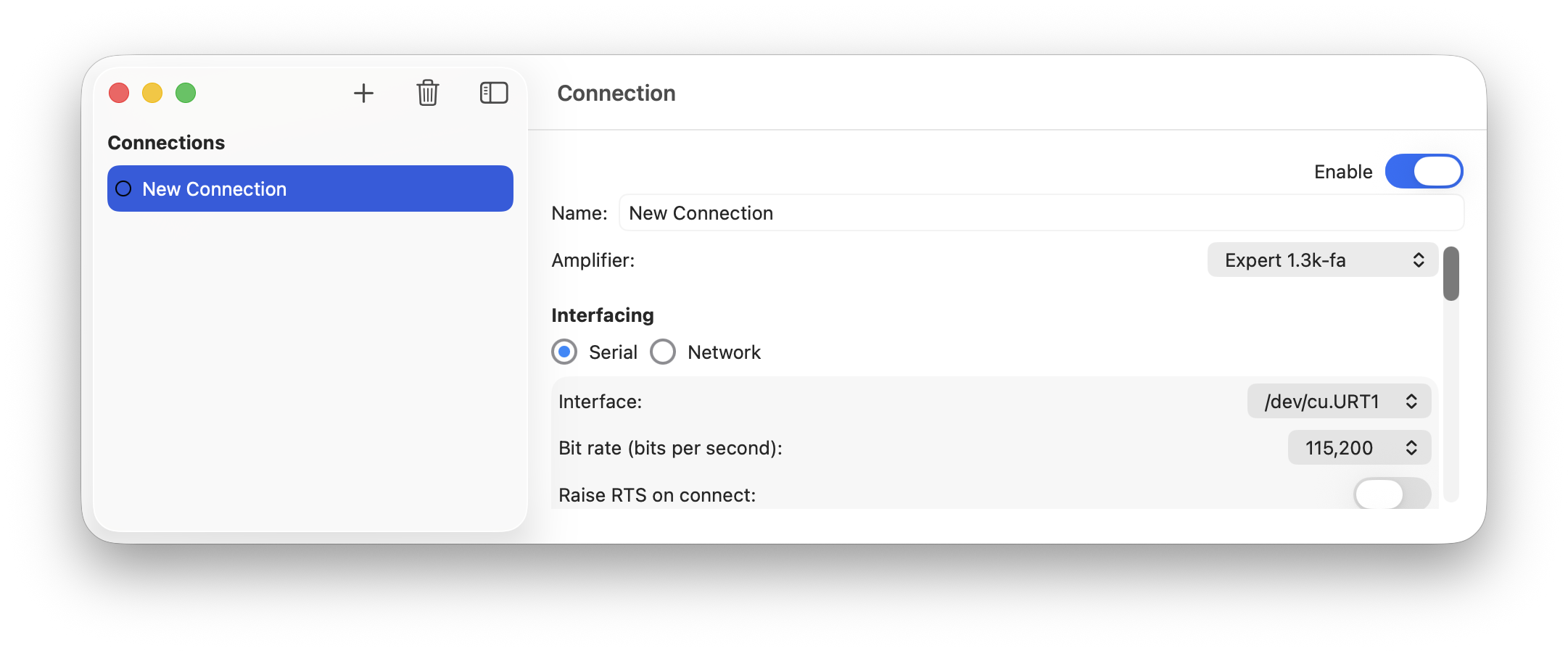
Connection maintenance
Creation
When the '+' / Plus icon is selected, a new Connection named 'New Connection' is created and added to the Connections list. If that Connection is then selected the right-side window pane is filled with all possible settings for a Connection. These settings may be tailored to suit the Connection being created.
See the next section for a detailed description of each setting.
Deletion
When a Connection listed in the Connections list is selected followed by the selection of the bin icon, the Connection is deleted.
Connection properties
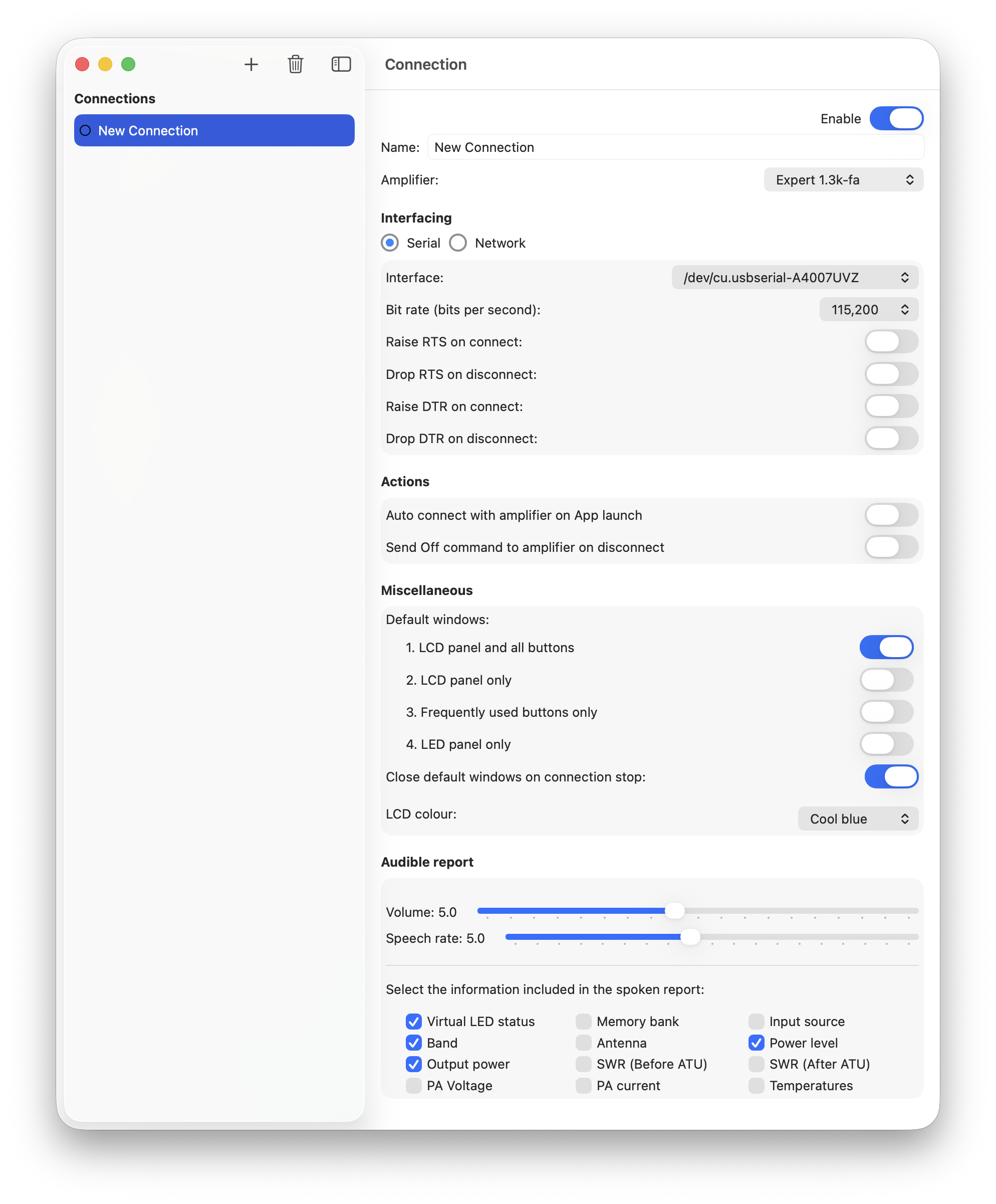
The Connection settings window contains many individual settings, also referred to as properties, that may be configured / tailored to meet operational needs; these are described in the remainder of this section.
The image below presents the entire Connection settings window and all settings that may be configured.
Enable
Default: Enabled
When a Connection is Enabled it may be started, stopped, woken or slept using the Activation manager. Disabling a Connection provides a way to hide Connections that are not used but wish to be retained for possible future use or reference.
Name
Default: ‘New Connection’
The name of the Connection. This should be a name that uniquely identifies this Connection. It is the name used to identify Connections in the Activation manager.
Amplifier
Default: ‘Expert 1.3K-FA’
Select the model of Expert amplifier connected to the interface identified by this Connection. When the model implements the Expert 1K-FA communications protocol the serial bit rate property is automatically set to a default of 9600bps.
Interfacing
Default: Serial
Select the type of interface to be used by this Connection: Serial or Network. Expert Controller Plus does not differentiate between USB and RS-232 serial interfaces; both are serial interfaces.
Serial identifies that Expert Controller Plus will use a Serial interface to communicate with the Expert amplifier.
Network identifies that Expert Controller Plus will use TCP/IP networking to connect to the Expert amplifier described by this Connection. As Expert amplifiers don’t implement a native network interface, Expert Controller Plus will use TCP/IP to connect to a network/serial adapter. The adapter must be configured and connected to the Expert amplifier using a serial connection.
Serial
When Serial is selected the following may be configured:
Interface
Default: The first interface identified by macOS
The macOS name of the serial interface connected to the Expert amplifier used for this Connection.
NOTE: for a serial interface to be listed and be available for selection it must be known to macOS. Additionally for a USB interface the amplifier must be awake and connected to the mac.
A list of serial interfaces known to macOS can be accessed using the drop-down list. Select the interface connected to the required Expert amplifier.
Bit rate (bits per second)
Default: 9600 (Expert 1K-FA), 115200 all other models
The rate - bits per second - at which data bits are transferred across the serial interface. Options ranging from 9600 to 230400 are available. The faster the selected rate the less time is required to transfer data between the amplifier and Mac. The default has been identified as sufficiently fast to achieve responsive results.
NOTE 1: This rate is different and not related to the CAT data rate used by Expert amplifiers on their CAT interfaces.
NOTE 2: For the Expert 1K-FA this should be 9600bps.
Wake / Sleep an amplifier
It is possible to wake an amplifier from sleep and return it to sleep using a signal on the RS-232 or USB interface. The RTS signal alone is sufficient to achieve this behaviour when a USB interface connects Mac to amplifier. When using an RS-232 interface, SPE documentation identifies that DTR should be used with DTR wired to the REMOTE ON pin of an amplifiers CAT interface. Expert Controller Plus enables RTS and/or DTR to be used for wake / sleep purposes.
Raise RTS/DTR on connect
Default: Off
A Connection may be configured to assert the serial RTS and/or DTR signals when it is started to wake an amplifier from sleep. If the connected amplifier is already awake, requesting that it awake using RTS and/or DTR has no effect.
When not selected, the amplifier must be awoken by an alternative method before Expert Controller Plus can establish communications. Alternative methods may include using the amplifier front-panel controls to ‘turn-on’ the amplifier.
Drop RTS/DTR on disconnect
Default: Off
This option ensures the serial RTS and/or DTR signal is not asserted when a Connection is requested by the user to 'Stop'. If an amplifier was awoken by raising the RTS and/or DTR signals, this will cause it to sleep.
NOTE: It has been observed that some serial interface hardware will not drop an RTS/DTR signal when software closes an interface and, for those, this option can force the signal to not be asserted prior to interface closure. However, most interface hardware appears to de-assert RTS/DTR when an interface is closed by software and, for those interfaces, this option will have no effect.
The functionality to de-assert RTS and/or DTR on disconnect is independent of, the ‘Send Off command on disconnect’.
Network
When the Interfacing selection is ‘Network’ the configuration options for serial interfacing are replaced with those for network interfacing.
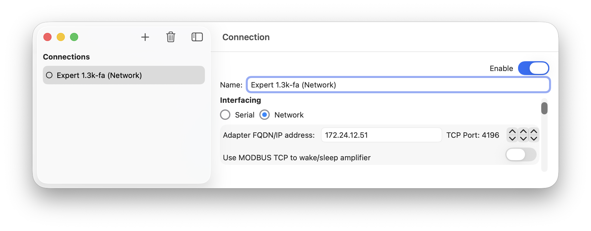
Adapter FQDN / IP Address
Default: 192.168.1.100
This is the Fully Qualified Domain Name or IP address of a network/serial adapter.
Examples of valid properties are:
192.168.1.100 (IPv4) or
fd00:192:168:111::100 (IPv6) or
waveshare.somedomain.org
Hostnames without a qualifying domain name suffix are not supported.
As information is typed it is validated by Expert Controller Plus. If the information is considered invalid it is coloured red.
NOTE: If the IP address or FQDN refers to a local network address macOS will request that permission be granted to Expert Controller Plus for it to access local network devices. It will request this permission just once, the first time a Connection is attempted, and will remember your choice thereafter. For Expert Controller to access a network/serial adapter connected to the local network it must be granted this permission. This permission may be later changed in the macOS System Settings | Privacy & Security | Local Network area.
TCP Port
Default: 4196
The TCP port number on which the network/serial adapter is listening for incoming connections from clients such as Expert Controller Plus.
Three sets of arrows permit the specification of port number. These adjust the port number in units of 1000, 100 and 1 from left to right respectively.
Use Modbus TCP to wake/sleep amplifier
Default: Off
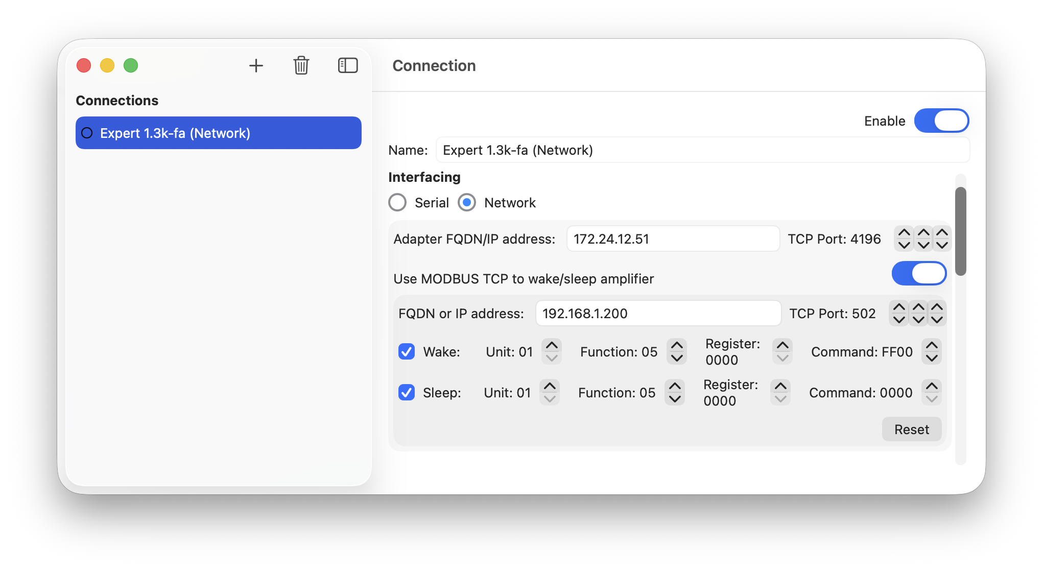
When a Connection uses a Network interface the serial, RTS/DTR signals are not available and it is therefore not possible to wake an amplifier using those methods. Modbus is a protocol that was standardised several decades ago which facilitates the control of relays and other such devices by computers. Put another way, Modbus standardises how to tell a remote device to do something by sending it a message and receiving a response. Modbus TCP is a variant of Modbus that uses a TCP/IP network to pass request/response messages.
Expert Controller Plus can use Modbus TCP to send commands to a Modbus TCP capable device such as a relay which can be used to signal an Expert amplifier to wake from sleep or to enter sleep.
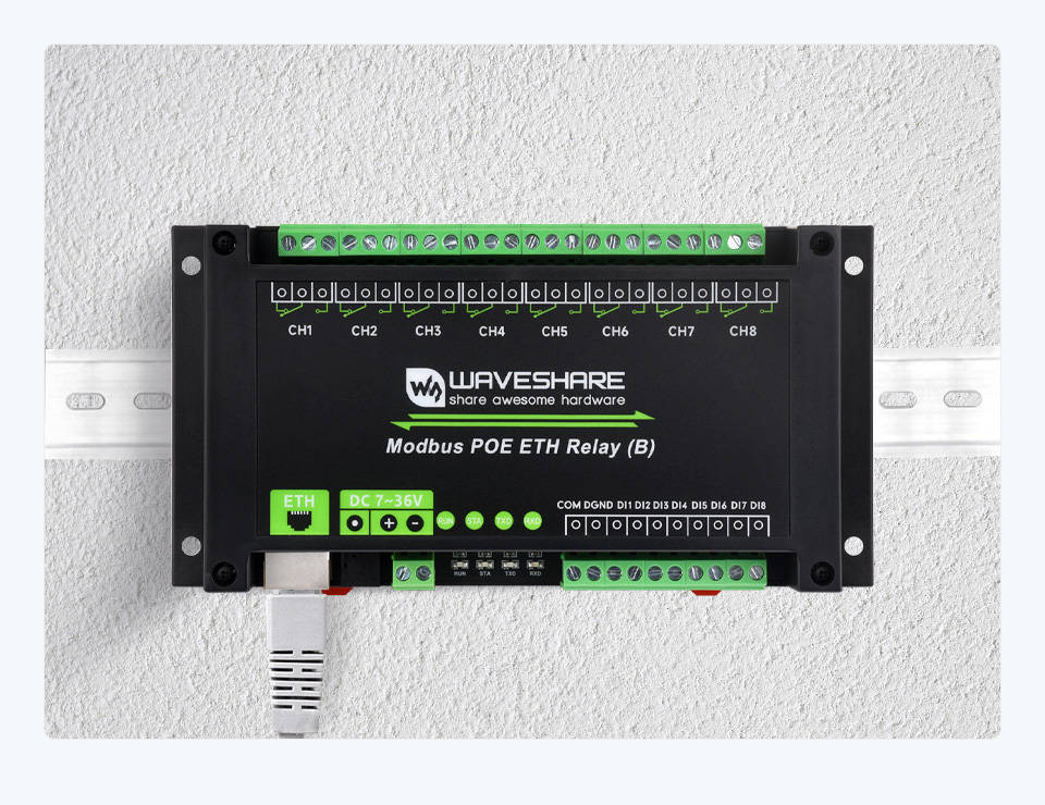
As Modbus is such a long standing protocol, it has widespread adoption by many devices useful in amateur radio. As an example Waveshare make a device they call the Modbus POE ETH Relay (B).
Further information regarding Modbus can be found at the following locations:
Adapter FQDN / IP Address
Default: 192.168.1.200
This is the Fully Qualified Domain Name or IP address of a Modbus TCP adapter.
Examples of valid properties are:
192.168.1.200 (IPv4) or
fd00:192:168:111::200 (IPv6) or
waveshare.somedomain.org
Hostnames without a qualifying domain name suffix are not supported.
NOTE: If the IP address or FQDN refers to a local network address macOS will request that permission be granted to Expert Controller Plus for it to access local network devices. It will request this permission just once, the first time a Connection is attempted, and will remember your choice thereafter. For Expert Controller to access a network/serial adapter connected to the local network it must be granted this permission. This permission may be later changed in the macOS System Settings | Privacy & Security | Local Network area.
TCP Port
Default: 502
The TCP port number on which the Modbus TCP adapter is listening for incoming connections from clients such as Expert Controller Plus.
Three sets of arrows permit the specification of port number. These adjust the port number in units of 1000, 100 and 1 from left to right respectively.
Wake and Sleep
Default: Wake Off, Sleep Off
For Wake and Sleep, Expert Controller Plus must be configured with the Unit, Function, Register and Command defined on your Modbus TCP device to achieve the actions you require. These values may vary between Modbus TCP devices and depend on the actions you wish to achieve. A full description of Modbus TCP is beyond the scope of this guide but it is well documented - see links above - and also the manufacturer of the Modbus device you use.
The defaults for Unit, Function, Register and Command were chosen as they are appropriate for switching on and off the Channel 1 relay on the Waveshare device identified above.
Unit
Default: 01
The unit identifier of your Modbus device.
Function
Default: 05
Function is a code that identifies the action the Modbus device is to perform.
Register
Default: 0000
The Modbus protocol defines four tables of registers: Coils, Discrete inputs, Input registers and Holding registers. Choose the Register appropriate to your needs and your Modbus device.
The default (0000), is in the Modbus coils table.
Command
Default: Wake FF00, Sleep 0000
The value appropriate for your intended action on your Modbus device.
On the aforementioned Waveshare device, FF00 closes the relay and 0000 opens the relay.
Actions
Auto connect with amplifier on App launch
Default: Off
When Expert Controller Plus starts, it scans all enabled Connections and will attempt to start any Connection that has this property set to: On. To stop a Connection from auto-starting when the application is started, set this property to: Off.
Send Off command to amplifier on disconnect
Default: Off
This option identifies whether Expert Controller Plus will send the amplifier an Off/Shutdown command when the Connection is stopped. Sending such a command will cause the amplifier to enter sleep.
If this option is selected and a Network interface is used, Expert Controller Plus always send the Off/Shutdown command. When using a Serial interface, Expert Controller Plus will only send the Off/Shutdown command if option ‘Raise RTS on connect’ option is not selected.
Miscellaneous
Default windows
Default: LCD and buttons only window
Expert Controller Plus supports five different amplifier view windows and it may be configured to open up to four of these when a Connection is started. Adjust the toggle associated to the desired amplifier view to either 'on' or 'off' as required.
The four windows types that may be configured are:
- LCD and buttons
- LCD only
- Frequently used buttons only
- LED panel only.
It is valid configuration to have no amplifier view windows opened when a Connection is started. When that is the case, the user must open the desired amplifier view windows manually using the macOS, File | New menu bar option prior to interacting with an amplifier.
Close default windows on connection stop
Default: On
When a Connection is stopped/closed all windows opened by default - see previous section - will be closed when this property is configured: On.
NOTE: Amplifier view windows opened manually are not affected by this option.
LCD Colour
Default: Cool blue
Expert Controller Plus has two windows that present a facsimile of the LCD display located on the front panel of an Expert amplifier. These are the LCD and Buttons window and the LCD only window. This property allows the virtual backlight of the LCD display in these windows to be changed. Four colours are supported: ‘Cool blue’, ’Warm white’, ‘Green black’ and ‘White black’.
NOTE: The selected colour scheme is for macOS Light mode only. When in macOS Dark mode the foreground text is always Green and the background, Black.
Audible report
This group of settings changes the behaviour and content of the audible report 'spoken' using Apple Voiceover.
Spoken report Volume and Rate
Default: Volume 5 / 50% and Rate 5 / 50%
The volume of the spoken report, relative to the master macOS volume, may be tailored. For example, when set at its maximum, the volume of the spoken report will be at the same level as the master volume set in macOS. By default, the volume is set to be 50%, a value of 5, that of the master volume.
The rate at which words forming the report are spoken may be adjusted using this control. The lower the value the slower the speech, conversely, the higher the value the faster the speech.
Content selection
The spoken status report comprises twelve components, each of which may be included or excluded as desired. By default four are included.
Virtual LED status
Default: Included
Two windows, ‘LCD and buttons’ and ‘LED panel’ contain multiple virtual LEDs. When selected the state of each virtual LED will be included in the spoken report.
Band
Default: Included
When selected the Band on which the amplifier is operating will be included in the spoken report.
Output power
Default: Included
When selected the instantaneous RF output power as reported by the amplifier is included in the spoken report.
PA Voltage
Default: Excluded
When selected the Voltage of the amplifiers, Power Amplifier sub-system is included in the spoken report.
Memory bank
Default: Excluded
When selected the memory bank currently in use by the amplifier is included in the spoken report.
Antenna
Default: Excluded
When selected the amplifiers, currently selected antenna is included in the spoken report.
SWR (Before ATU)
Default: Excluded
When selected the Standing Wave Ratio (SWR) prior to the amplifiers internal ATU is included in the spoken report.
PA Current
Default: Excluded
When selected the Current, expressed in Amps, of the amplifiers, Power Amplifier sub-system is included in the spoken report.
Input source
Default: Excluded
When selected the amplifiers input source is included in the spoken report.
Power level
Default: Included
When selected the power band (Min, Mid, Max) of the amplifier is included in the spoken report.
SWR (After ATU)
Default: Excluded
When selected the Standing Wave Ratio (SWR) after to the amplifiers internal ATU is included in the spoken report.
Temperatures
Default: Excluded
When selected the three temperatures - upper, lower, combiner - as measured by the amplifier are included in the spoken report.