Select one of the buttons below for further information.
RS-232 serial interfacing
The Wiki says:
In telecommunications, RS-232 or Recommended Standard 232[1] is a standard originally introduced in 1960[2] for serial communication transmission of data. It formally defines signals connecting between a DTE (data terminal equipment) such as a computer terminal or PC, and a DCE (data circuit-terminating equipment or data communication equipment), such as a modem.
The terms DTE and DCE are important as they help our understanding of RS-232 connector choice and cable wiring. Before IBM introduced the DB-9 connector on their PC range it was common to find DB-25 connectors. Today it’s rare to find equipment using a DB-25 connector for RS-232 interfacing as the world chose to follow IBM and standardise on the smaller DB-9 connector. That written, even today, some equipment uses a terminal block for RS-232 cable termination.
A DTE should present a plug, whether that be DB-9 or DB-25, and a DCE should present a socket. ‘Should’ is important as most equipment does follow this standard but it’s not universal. Even then some equipment manufacturers, in this case SPE, don’t follow the RS-232 standard wiring.
The transmission control of data on an RS-232 interface is typically achieved using hardware or software flow control. The most common hardware methods are: RTS/CTS (Ready/Clear To Send) and DTR/DSR (Data Terminal/Data Set Ready). Less common is XON/XOFF software flow control.
Most network/serial adapters appear to implement DTE but there is at least one I know of, PUSR USR-RS232-302, which implements DCE. There may be others that implement something non-standard so it’s best not to assume and confirm connector and pin usage before making a custom cable.
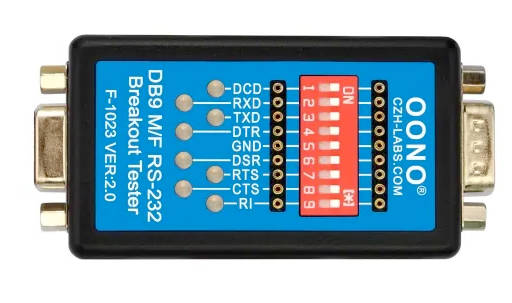
If, like me, you have a box of RS232 cables and you’re not sure whether any one cable is wired to be a null modem, straight-through or something completely different a simple LED tester is invaluable and can save lots of time and mistakes. These are inexpensive and available from a variety of suppliers. Alternatively, they make a small, basic-level project to build yourself.
SPE Expert ‘PORT’ interface
The management interface of SPE Expert amplifiers may be accessed using the USB (not relevant to this discussion) or an RS232 cable. The connecter for RS232 interfacing is a 9-pin ‘D’ socket and thus it could be assumed it implements a DCE interface. It DOES NOT! For the authoritative source of wiring see the SPE User Manual for your amplifier.
SPE amplifiers do not implement either hardware or software flow control on their RS-232 management interface. Hence only three wired connections are necessary: Tx data, Rx Data and signal ground. On the SPE amplifier, DB-9 PORT connector, these are: Pin 7 (Data from amplifier), Pin 8 (Data to amplifier) & Pin 5 (Ground).
DTE Network/Serial adapters
If the network/serial adapter implements a DTE interface using a DB-9 pin plug and it uses standardised pin-outs – as it should – then the wiring described below should apply.
| DTE DB-9 Plug pin | DTE Name | SPE Amplifier DB-9 Socket pin | Comment |
| 2 | RD | 7 | Data from amplifier to DTE |
| 3 | TD | 8 | Data to amplifier from DTE |
| 5 | GND | 5 | Ground |
If your network/serial adapter implements a DTE interface using a DB-25 pin plug and it uses standardised pin-outs – as it should – then the wiring described below should apply.
| DTE DB-25 Plug pin | DTE Name | SPE Amplifier DB-9 Socket pin | Comment |
| 3 | RD | 7 | Data from amplifier to DTE |
| 2 | TD | 8 | Data to amplifier from DTE |
| 7 | GND | 5 | Ground |
DCE Network/Serial adapters
For these adapters the above wiring will need adjusting to swap pins 2 & 3 on the network/serial adapter end of the cable only.